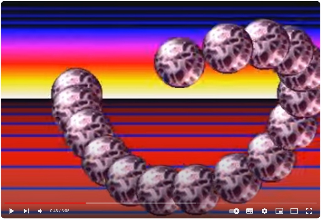
Recently I released a 4096 bytes Atari intro, featuring some bandwidth impossible sprites drawing in fullscreen. I hope technical inner details could please any graphics enthusiasts, and not only boomers :)
Audience
This post is made for anyone interested in oldskool graphics, but also for all retro computers technical details lovers. I will talk about STE blitter, and also how the ATARI famous “fullscreen mode” is working. Some assembly language concepts may be required for the last parts.
Table of Contents
I’ll try to split the post into several dedicated parts, so you can pick-up your favourite one!
- Atari STE specifications and memory bandwidth limit
- How the high level algorithm work
- Atari famous “Fullscreen”
- Using blitter in Fullscreen
- Final words
Atari STE specifications
Atari STE is a 8Mhz Motorola 68000 powered machine from the very end of the 80’. It features a 320x200 resolution. It can display up to 16 colors simultaneously. So the frame buffer is exactly 32000 bytes, or 31.25KiB. ( 4bits per pixel, using a weird bit-plane layout ). Most Atari come with 1MiB of RAM. (that’s not a typo, 1MiB RAM was luxury back in time)
In computer graphics during the 1990s, a common term was “sprite.” A sprite is a 2D bitmap that can be drawn anywhere on the screen. Typically, the term “sprite” refers to a “hardware sprite,” which is a bitmap displayed on the screen without being stored in the frame buffer memory. This approach is very fast because it eliminates the need to read from or write to the frame buffer. However, the Atari does not support hardware sprites. To move small bitmaps around the screen on an Atari, you need to “blit” them into the frame buffer. This means copying the bitmap into the frame buffer, erasing it in the next frame, and then blitting it again at a new position.
These types of graphics are known as “bobs,” short for “Blittable Objects.”
Speed of light
To understand the speed of an Atari machine, let’s examine some fast Atari blitter sprite code. In terms of 16-color bobs, the fastest example I know is a demo by Anima, which shows 24 bobs of 32x32 pixels each, running at 50Hz. Our bob is 64x64 pixels, which has four times the area of a 32x32 bob. This generally means it would be about four times slower (though the exact calculation is more complex, this is a reasonable approximation). So, the maximum speed for 64x64 bobs would be 24/4 = 6 bobs on screen. However, our intro displays 16 of them, and in fullscreen! Here is the video of our 4096 bytes demo:
( You can download the 4KiB intro here )
Given the memory bandwidth, this should be impossible! That’s exactly the reaction any demo coder wants from the audience: “How is that even possible?”
Like everything in the demoscene, there is a trick to it…
How the high level algorithm work
History
If you’re not from 90 you can’t imagine the amount of bitmap tricks used by pioneers. One of them is the stroboscopic effect. Just loop over 4 or more screens (you just change the frame buffer address) and you can get complex animation on screen for free. Of course the small amount of memory makes the animation loop pretty quick.
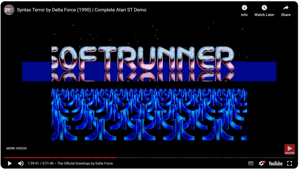
Here is an example of stroboscopic effect: All moving Atari logos in this video don’t cost anything. It’s a 8 frames looping animation. You get the feeling logos are scrolling smoothly. (Syntax Terror by Delta Force)
Unlimited Bobs
Relying on this stroboscopic effect, some Amiga freaks invented the so-called “unlimited bobs” technique. Just loop 4 or more screens. Each frame, draw a single bob. Don’t even clear it. In the next frame, draw another one, one step ahead.
When looking at the demo you have the feeling of an infinite amount of bobs drawn on screen. Obviously there is just a single one drawn each frame. Even if it’s a funny demo effect, it doesn’t fool the audience for long. After a while you’ll notice the screen has been filled with the same bob and the stroboscopic effect starts to kill your eyes.
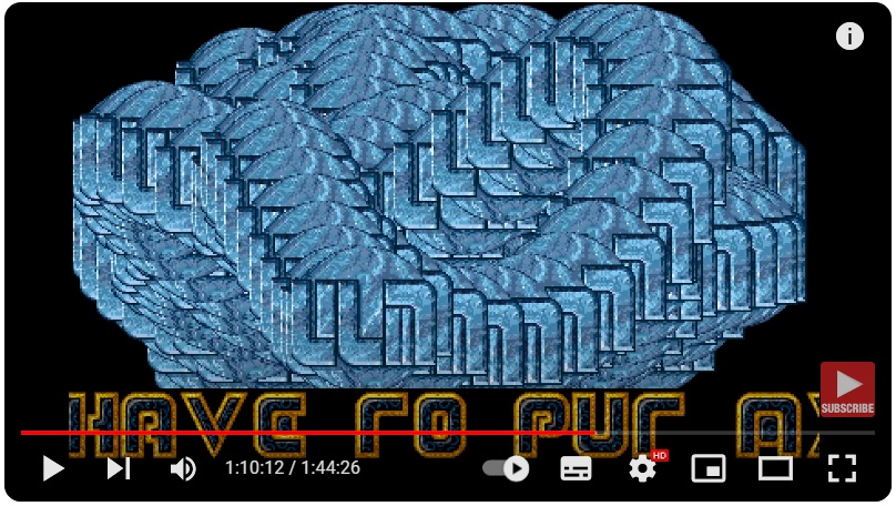
Here is an exemple of unlimited bobs (Dark Side of the Spoon by ULM, Atari)
The trick: Limited Bobs
Now let’s say I want 4 bobs on screen. Let’s use the unlimited bobs technique. (ie just display a single bob per frame, and use stroboscopic fx for movement illusion).
After 4 frames we have 4 bobs on screen. And now what if I can erase the oldest bob? It’s not as easy as it sounds because the erasing shape could be anything. The oldest bob is “under” all the others, so we have to erase the underlying part only. Let’s hand draw something to see what we should achieve

How to only clear the visible part of the very last bob? (The one under all the others)
Here is the trick:
In a off-screen buffer:
- Clear the area of the oldest bob in the offscreen buffer
- For N limited bob demo, draw the N-1 other bobs in this offscreen buffer, using OR
- Now the oldest bob offscreen area is a 1 color “mask”!
- You can apply this mask to the real screen, at the oldest bob location
- Compute the next coord of the new bob for the new frame
- Draw this new bob as a classic masked 16 colors bob
Here is outstanding quality hand drawing of the algorithm:
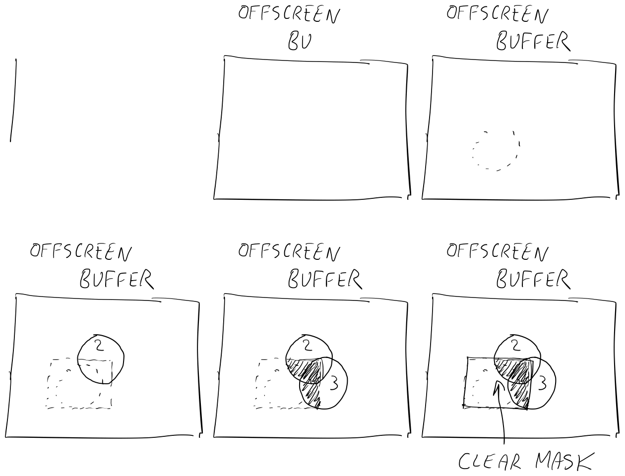
Then you just use this 1 color mask to clear the oldest bob on the screen by just applying a AND blit.
Why is it faster? Bitplans!
At the end we draw N bobs! ( N-1 at stage 2, and 1 at stage 6 ). So why the hell is it faster than just drawing N bobs?
Atari is a 16 colors, paletted machine. It means pixels are just indices in a palette ( exactly like 256 colors PNG file, or GIF file). You need 4 bits to encode a 16 colors index. Atari engineers could have encoded 2 pixels in a byte. But they choose the “bitplan” encoding scheme. If you’re not used to it, it’s quite confusing at first.
Each bitplan is a memory area that contains a single bit of the pixel index. Like, bitplan 0 contains all bits “0” of all the pixel indices. Bitplan 1 contains all bits 1, etc. As an exemple, the very first 2 bytes (16 bits) of bitplan 0 contain the bits “0” of the 16 first pixels of the screen.
When blitting a 16 colors bob, you have to run 4 complete blit operations. ( 1 per bitplan ). If you want to blit a 8 colors bob, you just need to 3 blit operations ( 8 colors means 3bits per pixel, so 3 bitplans only to fill)
Here is the trick: As the N-1 bobs are drawn in the offscreen buffer to create a 1 color mask, you only need a single blit operation! So the (N-1) single color bob OR drawing in offscreen buffer is 4 times faster than drawing 4bitplans bobs!
Atari famous “Fullscreen”
Back in time you can connect your Atari or Amiga to any CRT TV. And various TVs had various image position & scale setup. To guarantee graphics are visible, the 320x200 Atari image is in the middle of a very large “border”. You can notice the large white border all around:
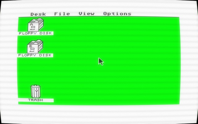
The Atari video chip, in charge of generating the video signal, is called “Shifter”. It supports only 3 screen resolutions:
- Low re: 320x200, 16 colors
- Medium res: 640x200, 4 colors
- High res: 640x400, monochrome (need a specific 70hz monitor)
And two refresh rates:
- 50hz ( Europe )
- 60hz ( U.S )
The Shifter is quite basic and not programmable. There is no way to display graphics bitmap into this large safety border. It’s just not possible. Even Atari hardware engineers that created the video chip didn’t even think about it.
If something is not possible you can imagine freaks from the demoscene will try to break the limits :) In late 80, some pioneer demo crews like Level16, Sync, ST-Connexion and others did the impossible! They displayed bitmap graphics in the safety zone! How the hell does it work?
Fooling the hardware with smart software
A classic scanline signal is made of 3 parts:
- Start of the left safety border, no bitmap graphics is displayed
- Few cycles later, start of actual screen bitmap graphics decoding and display image
- When 320 pixels are displayed, stop bitmap decoding, and start of the right safety border
Depending on the screen resolution and refresh rate, the shifter doesn’t build the exact same video signal. For instance, a low res 50Hz scanline is 512 cycles long, but a 60hz is 508 cycles. In high res, a scanline takes 224 cycles only.
To build the video signal each frame, the Shifter video chip is running a state machine. While generating the video signal, this state machine will tell the chip when to display the safety border, when to start to decode graphics, and when to stop to decode graphics.
Obviously this internal state machine isn’t documented. But thanks to the reverse engineering work or many people in the 90’ ( Alien, Troed, LjBK and others ) I can show you a high level view of the internal state machine of the video chip hardware:
If res=high and time=0 then start bitmap decoding
If rate=60 and time=52 then start bitmap decoding
If rate=50 and time=56 then start bitmap decoding
If res=high and time=160 then stop bitmap decoding
If rate=60 and time=372 then stop bitmap decoding
If rate=50 and time=376 then stop bitmap decoding
Note: “time” here is the cycle position within a scanline (so modulo 512 cycles). When the video signal goes to the next scanline, the “time” var used here goes back to 0
This state machine is hardcoded in the chip, you can’t change it at all. But what if you can change the video rate and resolution like a maniac at very specific points during each scanline?
Look at the internal state machine that is ending a standard low res 50hz line:
If rate=50 and time=376 then stop bitmap decoding
What if at the exact cycle 376 position you force the rate to 60Hz? The hardware will “skip” the “if” statement, and continue to decode the bitmap graphics! As you skipped the state where the chip stops to decode the graphics line, you just opened the right safe zone border! Of course, you have to go back to 50hz as soon as you can to avoid distorting the signal too much.
Now what if you set the resolution to high at cycle 0? The internal state machine will start the graphics decoding. Your monitor is unable to display a high res image? No problem, just go back to low res at the next cycle and you’re good!
So here is a 68000 assembly code that is fooling the shifter hardware to get rid of left and right safety borders, just for one rasterline
	move.w	a4,(a4)		// cycle 0: set the chip res to high to fool state machine!
	nop
	move.b	d6,(a4)		// cycle 12: go back to low res to avoid any image distortion
	nop
	nop
	...
	...		// wait during exactly 364 cycles (until cycle 376)

	...
	nop
	nop
	move.b	d6,(a5)		// cycle 376: set the rate to 60hz to fool state machine!
	move.w	a5,(a5)		// cycle 384: get back to 50hz to avoid distortion
	nop
	...					// wait during exactly 112 cycles (for next scanline)
	nop
Note: registers a4,d6 and a5 are pre-loaded with Atari specific address and values to change resolution and refresh rate
Of course you have to repeat this code snippet for every scanline you want to remove left and right border!
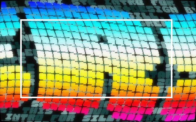
Note: Same kind of trick allows you to get rid of the top and bottom safety empty borders. At the end, you get a new screen resolution of about 416x274 visible pixels instead of the classic 320x200!
To get an idea of the new resolution here is a picture of a fullscreen demo. A white rectangle has been drawn to show approximately a standard Atari 320x200 resolution.
Note: As the CPU should stay in sync with the video decoding, it’s often called “racing the beam” technique. (reference to old CRT monitors where an electron beam was really moving from left to right during each scanline). When you repeat the code snippet above 274 times, almost all your time frame is wasted to fool the video chip. If you want to run your own code, you have to put it within all the “nops” instructions.
How to render bobs in the middle of that mess?
Any atari fullscreen fx should execute this code for each of 274 visible scanlines! Without missing a single cycle! For your own demo code, you only have two free slices of 364 and 112 cycles per scanline! You have to cut and divide your work into plenty of 364 and 112 cycle pieces! Your code should take the same time (no dynamic branch). If one single cycle is missing, the complete screen display is fucked up!
Regarding the extended fullscreen resolution, the screen buffer size is now 60KiB! Around twice bigger than normal. If you want to animate stuff on screen, it means you have to move twice as much memory!
That’s why doing a demo in fullscreen on Atari is really challenging!
Using blitter in Fullscreen
Atari STE has a custom chip called “Blitter”. This chip can do in hardware what the “bit blit” algorithm from the 70s does. Common use is to move or combine bitmap graphics. Basically it can operate bitmap graphics from rectangular areas. It can also do bit shifting, and various bit operations (or, and, xor, not, etc.). Atari STE blitter is much simpler than Amiga blitter (1 source instead of 3, not line drawing, no xor filling ) but still efficient. In the early days, people considered STE blitter almost useless. The amount of registers to set up before blitting is huge, so it wasn’t very efficient for small bitmaps. ( setup time was longer than proper blit operation).
Anyway STE Blitter can be a very efficient friend when used properly. Let’s see how a STE blitter 16 colors masked bob classic code works.
Drawing a Bob
A blitter only operates on words of 16 bits. Bitplan layout makes everything aligned to 16 pixels. As we want to draw bobs at any horizontal position (and not only 16 pixels aligned) we could use the blitter “shift”. And because of that we should also use one additional 16 pixels column. The final bob screen area will be 80x64 pixels

Blitter cost
What’s the cost of a blit OR operation on an 80x64 and 1 bitplan area? Let’s count the amount of 16bits words in the bob single bitplan mask: 5*64=320 words. Atari memory access timing is very easy: each word read or write is 4 cycles.
As we use a OR operation, the blitter have to do 3 memory access per bob bitmap word:
- Read the bob source data word from memory to internal register
- Read the background data word from memory and OR it into internal register
- Write the result back to the destination memory
Those 3 access takes 3*4=12 cycles. So the total cost is 5*64*12=3840 cycles. As a comparison, the electron beam takes 512 cycles to scan a line. So this 1 bitplan bob OR on screen is taking 7.5 scanlines of time. (Back in time we used to count timing in “scanlines”).
Blitter and fullscreen
Earlier we saw that we should slice all our code into small pieces of 364 and 112 cycles. When Atari blitter is running, the CPU is halted ( they don’t run in parallel ). So we have to “slice” the bob drawing into several small blitter commands. We could slice the bob in Y lines. The 1 bitplan OR takes 12*5=60 cycles for a 5 words bob line. The minimal blitter setup and run code is taking 28 cycles:
	move.w	#n,(a2)	  // set n number of lines to blit ( 12 cycles )
	move.w	d7,(a3)		// start the blit operation ( 16 cycles )
How many bob lines can we blit in the longest slice of 364 cycles?
(364-28)/60 = 5.6 lines. As you can only blit an integer number of lines, we can run the blitter for 5 bob lines. It will cost 5*60+28=328 cycles over our 364 cycles slice.
Applying the same for the second slice of 112 cycles we got
(112-28)/60 = 1.4 so 1 single bob line. We can use this fullscreen code block to blit 6 lines of the 1 bitplan bob during one scanline.
	move.w	a4,(a4)		// open left border
	nop
	move.b	d6,(a4)		// back to low res
	move.w	#5,(a2)		// blitter line count set to 5 (80x5 pixels)
	move.w	d7,(a3)		// run the blitter
	nop					// 9 nops (wait for 36 cycles)
	nop
	nop
	nop
	nop
	nop
	nop
	nop
	nop
	move.b	d6,(a5)		// cycle 376: open right border
	move.w	a5,(a5)		// back to 50hz
	move.w	#1,(a2)		// set next blitter line count (for 80x5 pixels)
	move.w	d7,(a3)		// run the blitter
	nop					// 6 nops (wait 24 cycles)
	nop
	nop
	nop
	nop
	nop
To draw our 64 lines height bob, we need to repeat this fullscreen code block 11 times. 10 first are drawing 60 lines of the bob, and the last code block should just set up blitter to draw the 4 last bob lines. So the real amount of time we spent to draw the bob is 11 scanlines of 512 cycles each = 5636 cycles.
Optimise, use the vertical blitter!
So we need 11 raster lines of time to draw the 64 lines bob in 1 bitplan. Can we do better? Yes! The first idea is to restart the blitter as soon as the previous work is done. Like, after drawing 5 lines, we could start the blitter to start “half of a bob line” maybe, to fill the time slice more efficiently? Unfortunately you can’t do that. Blitting a “part of the bob line” would imply you to set up tons of different blitter registers, such as line width, source line stride, dest line stride. It’s not worth it.
Around 2015 I did a lot of blitter in fullscreen for the -We Were @- demo. And I figured out an efficient technique to better fill the fullscreen time slices with the blitter. I called this technique “vertical blitter”. The idea is to draw the bob using vertical blocks of 16*N pixels. By doing this, the granularity of a blitter command will be 12 cycles (instead of 60 cycles for a complete bob line of 5 words).
The bob is drawn on screen using various size of vertical 16xN pixels strips:

Let’s rewrite the code using this technique. Now the blitter is setup to run on blocks of 16xN pixels, vertically
	move.w	a4,(a4)		// open left border
	nop
	move.b	d6,(a4)		// back to low res
	move.w	#28,(a2)	// blitter line count set to 28 (16x28 pixels)
	move.w	d7,(a3)		// run the blitter
	move.b	d6,(a5)		// cycle 376: open right border
	move.w	a5,(a5)		// back to 50hz
	move.w	#7,(a2)		// set next blitter line count (for 16x7 pixels)
	move.w	d7,(a3)		// run the blitter
In one raster line of time we draw a vertical bob column of 16*(28+7) pixels.
Devil is in details, once we have drawn a 16*64 pixels bob we have to reset the blitter destination address to proceed to the next bob column. So we need few instructions in between, and it will mess up the fullscreen timing a bit. Writing that kind of code manually is painful
Generating code!
If you look at my 4KiB intro, there is also a colourful background. It’s done by changing the background color every 3 scanlines. Again, it means you have to add an instruction every 3 scanlines to change the background color. And it will change all other blitter commands. Last but not least, the high level algorithm requires to change the blitter setup during the frame ( to clear the oldest mask bob, then to draw 1 bitplan bob, then to apply the mask into a 4 bitplans background. Then draw the final fully masked 4 bitplan bob)
To do this, I did a C program to generate a 68000 assembly code, doing all the nasty timing computation for me. It generates a 4000 lines assembly source file with the right blitter commands, at the right place in between the fullscreen resolution & refresh rate change. Here are just a few lines of the generated source code so you can get how every cycle is counted. Also how the fullscreen hardware fooling code should explicitly fall at 0 and 376 cycle. If only one is missing, you won’t see anything on screen but garbage.
	move.w	#7,(a2)	// set blitter line count to 7	// [12 cycle]
	move.w	d7,(a3)	// run blitter	// [100 cycle]
// Raster line 42 [0]
	move.w	a4,(a4)	// cycle 0: set high res, open left border	// [8 cycle]
	nop	// [4 cycle]
	move.b	d6,(a4)	// back to low res	// [8 cycle]
	move.w	#28,(a2)	// set blitter line count to 28	// [12 cycle]
	move.w	d7,(a3)	// run blitter	// [352 cycle]
	move.b	d6,(a5)	// cycle 376, set 60hz to open right border	// [8 cycle]
	move.w	a5,(a5)	// back to 50hz	// [8 cycle]
	move.w	#5,(a2)	// set blitter line count to 5	// [12 cycle]
	move.w	d7,(a3)	// run blitter	// [76 cycle]
	nop	// [4 cycle]
	nop	// [4 cycle]
	move.w	(a1)+,$ffff8240.w	// change background color	// [16 cycle]
// Raster line 43 [0]
	move.w	a4,(a4)	// cycle 0: set high res, open left border	// [8 cycle]
	nop	// [4 cycle]
	move.b	d6,(a4)	// back to low res	// [8 cycle]
	move.w	#23,(a2)	// set blitter line count to 23	// [12 cycle]
	move.w	d7,(a3)	// run blitter	// [292 cycle]
	move.w	(a0)+,d1		// dst	// [8 cycle]
	move.w	(a0)+,d0		// src	// [8 cycle]
	// bitplan #0
	move.w	d0,$ffff8a26.w	// [12 cycle]
	move.w	d1,$ffff8a34.w	// [12 cycle]
	move.w	#8,(a2)	// set blitter line count to 8	// [12 cycle]
	nop	// [4 cycle]
	nop	// [4 cycle]
	move.b	d6,(a5)	// cycle 376, set 60hz to open right border	// [8 cycle]
	move.w	a5,(a5)	// back to 50hz	// [8 cycle]
This is just a small part. If you’re curious, the complete assembly source code for blitter rendering this 4KiB intro can be seen here:
Have a look at the generated 4000 lines fullscreen blitter code
Final words
This post is long enough to stop here. I hope you enjoyed reading it, and maybe learned something as a bonus!
I may do a second post to talk about
- How to fit the 2 minutes music into the 4KiB intro
- How to fit the code (esp the 4000 lines assembly source) in 4KiB
- Some words about best practice to please your face exe packer
Knowing good tricks on old machines sometimes could inspire you to invent some new techniques on modern hardware!
