Audience
This post is for any enthusiastic SIMD CPU programmer curious about weird AVX instructions. But also for any veteran Amiga programmer who never quite figured out how to calculate that cursed “minterm” blitter value!
AVX-512 Bitwise ternary logic instruction
The idea for this post came while watching a great talk by Tom Forsyth [1] about the design of the AVX-512 ISA (Instruction Set Architecture). As I quickly skimmed through the slides, I paused at slide 41, where an obscure instruction caught my eye: vpternlogd (yeah, Intel engineers aren’t known for their naming skills!).
This instruction is a bitwise ternary logic operation, meaning it can perform any bitwise Boolean logic using three input sources. For example, if we label the inputs A, B, and C, you can create any complex logic operations like:
(NOT A) OR ((NOT B) XOR (C AND A))
Or any other boolean logic combination you need—all in a single instruction!
What’s even cooler is that the inputs can be 512-bit registers, allowing this complex logic to be performed on 512 bits at once.
The author explained that adding specific instructions for every possible user needs (like “foo_and_a_or_not_b”) would have been overwhelming. It would require tons of new mnemonics, documentation, and testing. Instead, they opted for a smarter (and lazier?) solution: a single, flexible instruction:
VPTERNLOGD r0, r1, r3, #imm8
The instruction takes 3 registers as input, and an 8-bit immediate value that defines the exact bitwise operations to do. Unfortunately, most documentation just says, “The immediate value determines the specific binary function,” which isn’t very helpful.
As soon as I saw this 8-bit immediate value, it reminded me of an old friend from 1985: the Amiga blitter chipset!
Amiga blitter custom chip
In the 1980s, it was common for computers to have custom chips for handling graphics. However, these chips didn’t handle complex tasks like triangle rasterization or programmable shaders. At that time, “graphics” primarily meant working with bitmaps. For example, the Commodore Amiga 500 had a blitter chip. Its main function was to move bitmap graphics from one location to another while applying logical operations. The Amiga’s blitter could handle up to three bitmap sources at once and perform logical operations between them. To specify which operation to use, you needed to set an 8-bit value in the chip, known as the “minterm.”
Three bitmap sources and an 8-bit value to control logical combinations! Doesn’t that sound like a primitive version of the modern AVX vpternlogd instruction?
Interestingly, even many skilled Amiga programmers didn’t know how to calculate the minterm value. Most just reused common values from other demos. For instance, to clear a buffer, they would use 0x00. To configure the blitter to draw masked sprites, they’d use 0xE2. But for any other weird custom function, most of us were lost back in time.
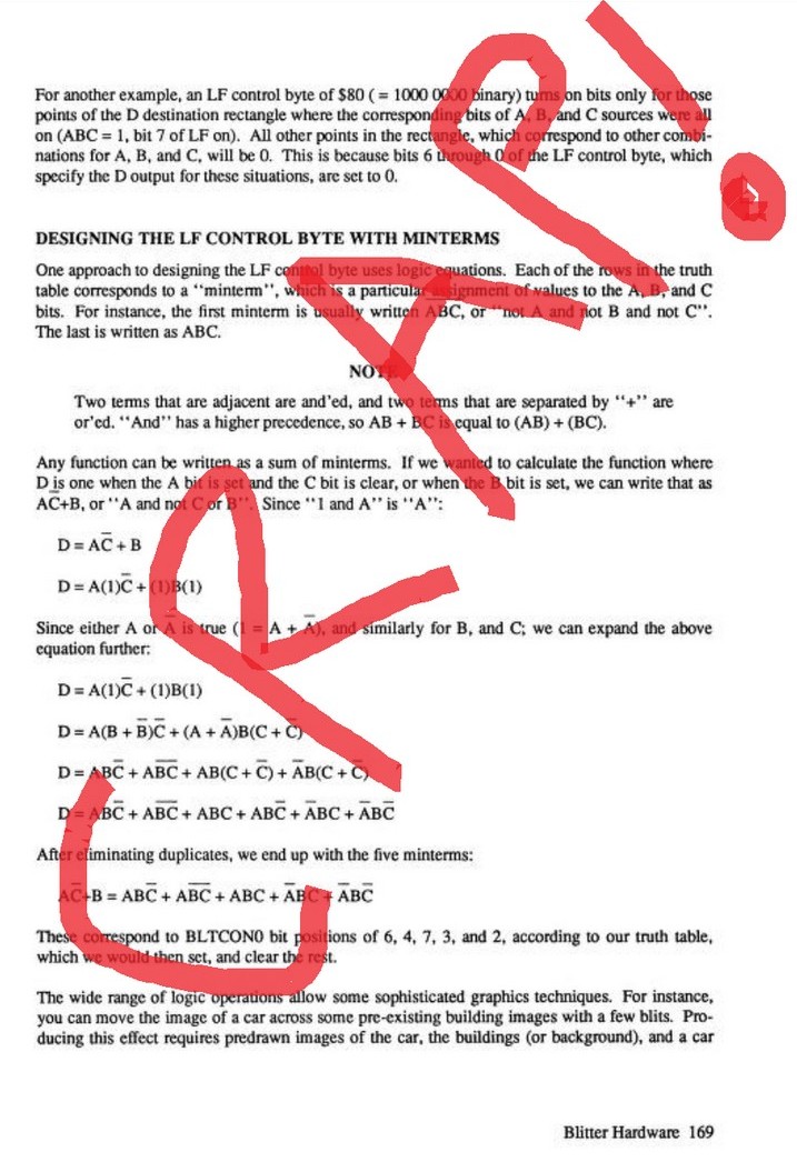
The Amiga blitter user manual didn’t help much either. The “Amiga Hardware Reference Manual” from 1989 tried to explain minterm calculation using confusing symbols, which frustrated many young demo makers at the time.
Here’s what my teenage self would have done with a red marker if I had the official documentation in hand :)
Easy way to calculate minterm value
Now, let me show you an easy way to calculate the minterm value. Even if you’re not planning to program the Amiga blitter anytime soon, you might find this useful for working with modern AVX ternary logic instructions—they work exactly the same way!
A few years ago, I realized that this 8-bit value doesn’t have to be understood as just a set of logical operators. Instead, it’s fundamentally just a lookup table.
Let’s take an example: suppose you want the result to be 1 when exactly two of the three sources are 1.
First, list the 8 possible values of three input bits (A, B, and C), and add a fourth empty column for the result.
| A | B | C | what I want |
|---|---|---|---|
| 0 | 0 | 0 | ? |
| 0 | 0 | 1 | ? |
| 0 | 1 | 0 | ? |
| 0 | 1 | 1 | ? |
| 1 | 0 | 0 | ? |
| 1 | 0 | 1 | ? |
| 1 | 1 | 0 | ? |
| 1 | 1 | 1 | ? |
And now just fill the fourth column with the exact result you want your function to do. For our specific example, we want 1 when exactly two sources are 1. Let’s fill the fourth column:
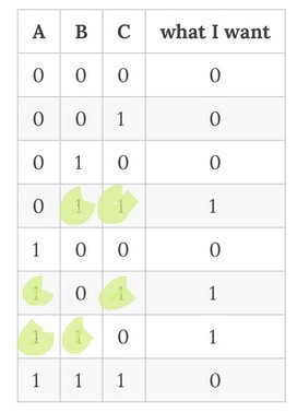
And now the magic: read the 8 bits of the fourth column, from bottom to up: 01101000, or 0x68. Function 0x68 will set 1 as a result if exactly 2 inputs are 1.
And you also got the mysterious #imm8 value of the modern vpternlogd instruction!
You can use the exact same method to get the #imm8 value for any exotic or complex logical function between 3 sources you need.
I wish my younger self had known this method back when I was scratching my head over blitter minterms!
A funny coincidence
One of the very common Amiga minterm values is 0xE2. This value is often used to render masked 2d sprites. With A containing the sprite bitmap, B containing the sprite “mask”, and C being the background.
An easy way to calculate the minterm for a masked sprite is to think of it in simple programming terms: when the mask pixel (B) is set, the result is sprite (A). If the mask pixel is not set, the result is background (C)
| A | B | C | what I want |
|---|---|---|---|
| 0 | 0 | 0 | 0 (B is not set, use C) |
| 0 | 0 | 1 | 1 (B is not set, use C) |
| 0 | 1 | 0 | 0 (B is set, use A) |
| 0 | 1 | 1 | 0 (B is set, use A) |
| 1 | 0 | 0 | 0 (B not set, use C) |
| 1 | 0 | 1 | 1 (B not set, use C) |
| 1 | 1 | 0 | 1 (B is set, use A) |
| 1 | 1 | 1 | 1 (B is set, use A) |
Read the 8 bits bottom to up: 11100010, or 0xE2
So 0xE2 is a very common minterm value in Amiga demoscene culture. And now the funny part of this post:
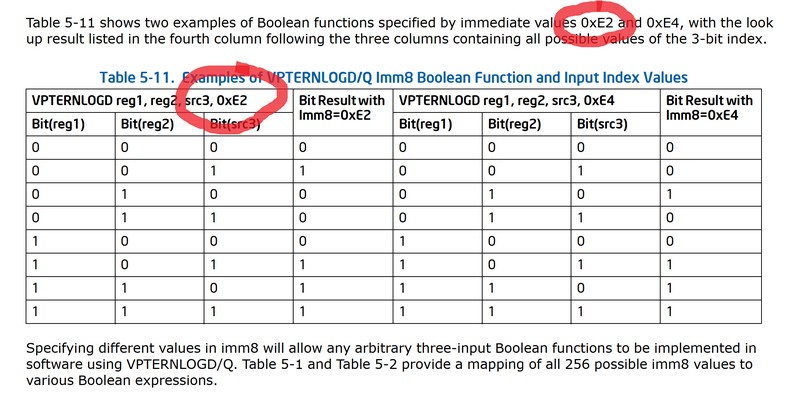
The official Intel documentation [2] about vpternlogd has an example of a #imm8 value. And over the 256 possible user functions they could have chosen, I’ll let you discover what they chose :)
Conclusion
Is there any Amiga fanboy in the Intel documentation example team? A bit of retro influence never hurts! :)
Links
[1] Tom Forsyth presentation about AVX-512 ISA design
[2] Intel 64 and IA-32 Architectures Software Developer’s Manual